Fire Pump Room Layout and Requirements Explained Simply and Practically
A fire pump room is the heart of a building’s fire protection system. If the pump room fails, hydrants and sprinklers lose pressure, water flow drops, and firefighting efforts become ineffective. Many serious fire incidents have escalated not because pumps were absent, but because the pump room layout was poorly designed, poorly ventilated, or difficult to access during emergencies.
According to HSE fire and explosion guidance, fire protection installations must be suitably designed, accessible, and maintained to ensure effective operation during emergencies.
This guide explains how a fire pump room should be laid out and why each requirement exists, using practical explanations instead of code language. It is written for safety officers, facility managers, engineers, supervisors, and building owners who need to understand how a pump room actually works during a fire.
Why the Fire Pump Room Is So Important
During a fire, water demand increases suddenly and dramatically. The fire pump room ensures that:
- Water reaches hydrants and sprinklers at sufficient pressure
- Flow remains stable for long firefighting durations
- Backup systems activate automatically if power fails
If the pump room layout is incorrect, even the best fire pumps may fail under emergency conditions.
What Happens Inside a Fire Pump Room During a Fire
When a hydrant or sprinkler opens:
- System pressure drops
- The jockey pump attempts to stabilize pressure
- If pressure continues to fall, the main fire pump starts automatically
- If power fails, the diesel pump starts without human intervention
All of this must happen without delay, which is why layout, accessibility, and ventilation are critical.
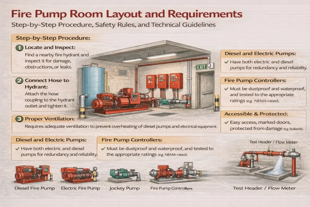
Main Equipment Found in a Fire Pump Room
A typical pump room contains:
- One electric fire pump
- One diesel fire pump
- One jockey pump
- Pump controllers and electrical panels
- Suction and discharge piping
- Pressure gauges and monitoring devices
Each component has a specific role, but their physical arrangement determines whether they can operate reliably.
Why Pump Room Location Matters
A fire pump room should:
- Be located close to the fire water tank
- Allow gravity-fed suction where possible
- Remain accessible during emergencies
- Be protected from flooding and external damage
When pump rooms are placed too far from water sources or above tank level, pumps struggle to draw water, leading to pressure loss or cavitation.
Space and Clearance Requirements Explained
Adequate space is not a luxury, it is a safety requirement.
Proper spacing ensures:
- Technicians can access pumps during maintenance
- Valves can be operated quickly during emergencies
- Heat from motors and engines can dissipate
A cramped pump room often leads to:
- Delayed repairs
- Unsafe working conditions
- Overheating of diesel engines
Why Pump Foundation and Alignment Are Critical
Fire pumps operate at high speed and pressure. Improper foundations cause:
- Excessive vibration
- Coupling misalignment
- Bearing failure
- Pipe stress and leakage
A solid concrete foundation with proper anchoring ensures smooth and long-term operation.
Understanding Suction Pipe Layout in Simple Terms
The suction pipe delivers water from the tank to the pump.
If the suction layout is poor:
- Air enters the system
- Water flow becomes unstable
- Pump impellers get damaged
Best practice includes:
- Short, straight suction piping
- Larger diameter than discharge piping
- Minimal bends near the pump
Good suction design prevents cavitation, one of the most common causes of pump failure.
Why Discharge Pipe Arrangement Is Just as Important
The discharge pipe carries pressurized water to the hydrant or sprinkler system.
Poor discharge design can cause:
- Pressure fluctuation
- Water hammer
- Pipe rupture
Smooth transitions, proper valves, and pressure gauges help maintain system stability during sudden demand.
Importance of Test Lines in Pump Rooms
Fire pumps must be tested regularly under load.
Test lines allow:
- Flow testing without activating the entire fire system
- Verification of pump performance
- Detection of pressure loss or mechanical issues
Without proper test lines, pump performance remains unknown until an actual fire occurs.
Electrical Supply and Backup Power Explained
Fire pumps must never depend on normal building power alone.
A reliable system includes:
- Dedicated electrical feeders
- Automatic pump start
- Backup diesel operation
If power fails during a fire and no diesel backup exists, the entire fire protection system becomes useless.
Diesel Pump Ventilation Is Not Optional
Diesel engines generate:
- Heat
- Exhaust gases
- Combustion fumes
Without proper ventilation:
- Engines overheat
- Automatic shutdown occurs
- Fire protection fails at the worst moment
Ventilation openings and airflow paths must be designed to remove heat efficiently.
Lighting and Visibility Inside Pump Rooms
During emergencies:
- Visibility may be poor
- Smoke or water may be present
- Fast decisions are required
Adequate lighting ensures:
- Safe movement
- Quick valve identification
- Accurate monitoring of gauges
Emergency lighting is strongly recommended.
Why Storage Is Not Allowed in Pump Rooms
Pump rooms are often misused as storage spaces.
This is dangerous because:
- Combustible materials increase fire risk
- Stored items block access to valves
- Equipment damage occurs during emergencies
A pump room must remain clean, dry, and dedicated solely to firefighting equipment.
Drainage and Flood Protection
Water leakage during testing or fire events is common.
Proper drainage prevents:
- Electrical damage
- Slippery surfaces
- Corrosion of equipment
Pump rooms without drainage often suffer long-term reliability issues.
Monitoring and Alarm Systems
Modern pump rooms include indicators for:
- Pump running status
- Pressure levels
- Power failure
- Diesel engine faults
These indicators help operators respond quickly and prevent unnoticed failures.
Common Pump Room Layout Mistakes
Many failures result from avoidable mistakes such as:
- Installing pumps above water tank level
- Long suction pipes with multiple bends
- Inadequate ventilation for diesel engines
- Poor access to valves and panels
These issues often remain hidden until a fire drill or real emergency exposes them.
Why Regular Inspection Matters
Even a well-designed pump room requires regular checks.
Routine inspections help detect:
- Pressure instability
- Battery failure in diesel pumps
- Blocked ventilation paths
- Valve seizure or leakage
Small issues, if ignored, can lead to complete system failure during a fire.
Real-World Lesson From Fire Incidents
Many post-fire investigations reveal that:
- Pumps were installed but not accessible
- Diesel engines overheated due to poor ventilation
- Valves could not be operated quickly
In almost every case, the root cause was layout and planning, not lack of equipment.
Conclusion
A fire pump room is not just a mechanical space, it is a life-safety system that must work flawlessly under extreme conditions. Proper layout ensures reliable water supply, safe maintenance access, effective ventilation, and automatic operation when human response time is limited.
A well-planned pump room improves:
- Fire response effectiveness
- Equipment life
- Safety of occupants and responders
- Compliance with fire safety expectations
When a fire occurs, the pump room becomes the unseen force that determines whether firefighting succeeds or fails.
Fire Hydrant System: Components, Working, Types, Installation and Maintenance
Components of a Fire Hydrant System: Detailed Explanation of Parts and Functions
How to Operate a Fire Hydrant: Step-by-Step Procedure, Safety Rules, and Technical Guidelines